Digital Logic and Circuit Schematics
The Raspberry Pi's inputs and outputs use digital logic. This is a type of electrical signal where it is either HIGH or LOW. High for the Raspberry Pi corresponds to 3.3V. Some other microcontrollers like Arduinos use 5V as HIGH. LOW corresponds to 0V (or ground).
Schematic Overview
Electrical circuits can be dscribed by Fritzing diagrams ("exact" illustrations) or by schematics. Schematics use different symbols to represent different components. If you find a circuit diagram in a textbook or on a website, its likely to be in schematic form, so its useful to understand how they work.
Lines in the schematic connect the components, representing wires in the circuit. Sometimes lines in the schematic may intersect. If the intersecting lines have a dot on the intersection, it means wires actually connect at that point. Otherwise, there is no connection, and the crossing occurs in the diagram only.
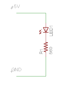 In this example, Pin 18 connects from the Raspberry Pi directly to LED. The other lead of the LED is connected to a resistor, which goes to Ground.